 German
| General Preface Schematic Download back to my projects General
|
 |
| Simple joysticks are available
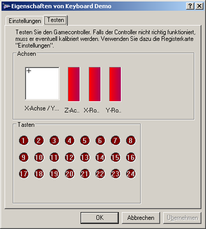
for little money. There is no need to build your own one. But sometimes it makes sense to build your own individual joystick. Especially the flight simulation enthusiasts like to build cockpit parts with the look and feel of original aircraft parts. Such self made hardware needs an joystick controller that meets the requirements of the hobbyists. This project is ideal to build up devices with up to 5 axis and 24 buttons. It is based on the microcontroller PIC18F2455. I was inspired by a project on opencockpits.com. There is used the outdated PIC16C745 to design a similar project. The operating system of any modern PC recognizes the device as a joystick with 3 additional axis (sums up to 5 axis) and 24 buttons, not needing additional software or driver. |
 |
| The joystick-controller is
powered and controlled via USB. The capacitors C1 and C5 stabilize the
supply voltage. C2 is stabilizing the USB-voltage if the internal
3.3V-voltage regulator. Q1, C3 and C4 feed the microcontroller with a stable 20-MHz clock. R1 pulls up Pin 1 of the microcontroller to high level. The circuit is designed for a PIC18F2455. However, PIC18F2458/2550/2553 can be used as well. (No changes at the hardware or HEX-file would be necessary.) Axis To every 3-pin-connector SV1 bis SV5 can be hooked up a linear 10-kOhm-potentiometer (the resistivity value is non critical). The sliding contact of the potentiometer has to be connected to pin 3 of the connector. The end-contacts of the potentiometer have to be connected to the pins 1 and 2 of the connector. The following circuit shows a single potentiometer.  |
 |
| Buttons The buttons are connected between SV6 and SV7. The 24 buttons are organized in a matrix with 3 rows and 8 columns. |
 |