For a quick start just download this ZIP-File with all necessary data. It contains a handbook in English language.
To observe air traffic one needs:
|
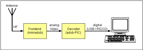 |
| The transponder signals are
vertical polarized. A vertical polarized antenna tuned to 1090 MHz is
required to receive this signals. The simplest solution is a vertical
wire or metal stick of 13 cm length , this is the half wavelength of
the 1090 MHz signal. Such an antenna is an electric dipole and receives
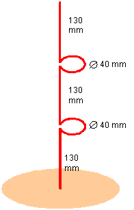
signals from all directions. To improve the antennas sensitivity multiple electric dipoles can be combined. But if they are placed side by side, then the antenna would not be an omnidirectional antenna anymore. Consequently the individual dipoles have to be placed about each other. Finally the dipoles have to be interconnected, but upper and lower end of each dipole oscillate with 180 degree phase shift. To connect them 130mm long horizontal loops have to be used. They work as 180 degree phase shifter. Dipoles and loops should be bended from one long piece of wire. Its diameter should be large enough for the necessary stability.. The lowest point of this dipole-group has to be connected to the middle wire of an 50-ohms coaxial cable. Now we need a "dummy-ground", that has to be connected to the shield of the coaxial cable. A round piece of sheet metal (13 cm radius) would be great, but some radial wires can be used instead. At least 4 wires (90 degree interspaced) should be used (groundplane-antenna). "Dummy-ground" and dipole don't have to touch each other! This is just a basic design. The impedance of the antenna is not matching the impedance of the cable (but can be modified by bending the "dummy-ground"-wires downwards. Longer or shorter connection loops between the dipoles can change the elevation angle of the antenna ....... Antenna design requires knowledge, experience and luck. |
 |
| To receive ADS-B-signals a 1090
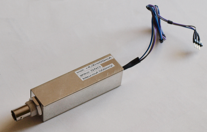
MHz receiver is needed. I use the direct detection receiver miniadsb from jetvision.de. It can be ordered as
kit at http://miniadsb.web99.de/
for 45 Euro. To build the kit together requires experience in
SMD-soldering. The whole receiver has the size of a textmarker (2cm x
2cm x 8cm). The input is a coax connector for the antenna cable. The
output for the received signals is an analog output. Beside the antenna connector, the decoder has 3 connection-wires only.:
The analog output can deliver up to 0.4 mA. It should never be connected to any voltage, because it can be easily damaged. The value of the supply voltage influences the receivers sensitivity. The optimum is 4V. Voltages larger then 5V or voltages of wrong polarity will destroy the receiver. For safety reasons i placed a Schottky diode inside the receiver. It is in line with the power supply wire (prevents wrong polarity) and increases the optimum voltage at the power supply wire to 4,5V. This voltage will be produced by my decoder. |
 |
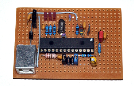
| The picture at the right site
shows the whole decoder on a universal board. It is made up from a
small number of parts. With SMD-parts the
decoder fits on a 4cm x 4cm PCB (single sided). The one and only active part is the PIC microcontroller (PIC18F2455 or PIC18F2550). Its comparator converts the analog signal into a digital signal. The comparator needs a reference voltage. This reference voltage is produced by the decoder itself. The PIC18F2550 searches in the digitized signal for ADS-B-data and reads this data. Transponders send many different ADS-B-frames. The most valuable frames ate DF17-frames. DF18 and DF19 would be of same value, but are rarely transmitted. The decoder can forward all data to the PC or only DF17/18/19-frames. |
 |
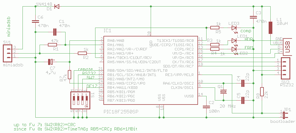 |
The digitized signal leaves the comparator at pin 6 and is immediately fed back into the PIC at pin 11. Pin 11 is the digital ADS-B input of the micrcontroler. If somebody likes to use a separate comparator, then the connection between pin 6 and pin 11 has to be removed, and the digital signal from the external comparator would have to be fed into pin 11. |
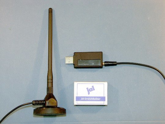 |
Not all aeronautic enthusiasts
are electronic hobbyists too. There are some industrial products on the market. I just test out the GNS5890-USB-stick. The GNS5890 is smaller then a matchbox and contains the ADS-B-receiver and the decoder. An antenna with 1 meter long antenna cable is included. This set is ideal for mobile use. The decoder is fully compatible to my adsbPIC-decoder, and will be delivered with the (relabeled) firmware 8. To use it with adsbScope the CDC-driver has to be installed. You can use the driver-CD of the GNS5890 or my ZIP-file (since 16.12.2011). After driver installation the GNS5890 is supported by Planeplotter too. The GNS5890 is a very strait design without any frills. It has no DIP-switches, RS232-interface or input for external comparator. This made it possible to shrink the size. The result is a capable and reliable device. During the first tests if outperformed my receive chain (a stocked triple dipole antenna, miniadsb-receiver and adsbPIC-decoder). The frame rate was 20% up to 100% higher, and more aircraft have been tracked. I pimped my miniadsb-receiver a little bit, and now both systems are comparable. Source Global Navigation Systems – GNS GmbH |